
Proposed Timeline

Proposal
Design
Proposed Budget
Progress Log
Week 13 (11/26/20 - 12/02/20)
We started the week by meeting up to get videos and final results for Easy Tree. We recorded several videos of Easy Tree, and finalized the report and submitted on November 27th. The report can be found under the Design Documents tab.


The rest of the week has been focused on finalizing the report. We have been practicing the presentation every day. The presentation can be found under the Documents tab
Week 12 (11/19/20 - 11/25/20)
We spent most of this week working on the report and trouble shooting/ integrating modules. It was determined after many hours that the GPS would need to be dropped in favor of a preprogrammed driving path. The fertilizer, seed dispensor, drill, and driving codes were all finalized and integrated to the code.

Above shows some pictures and videos of the SD card module plugged in and working. The pH values were properly writing to the SD card and this is great news! The rest of the short week was spent fixing coding issues and working on the paper. We are near complete on Easy Tree just need a final video for presentation of it working.
Week 11 (11/13/20 - 11/19/20)
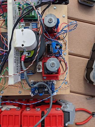
We first started by meeting up to mount the last hardware devices to the chassis. We prioritized fertilizer pump and the limit switches along with the pH probe. Below are two videos showing two different tests of the fetilizer pump, in one of these videos the pump happened to drain the bottle of all the liquid, in the other video gravity stopped the pump from further draining all the liquid. We have solved the reason as to why the pump would always drain. The solution is that the tube needs to be kept above water level.
Another minor thing we did this week was add a saftey switch for the power supply of the robot. We just added a SPST switch in series with power. This can be seen in the picture below, right next to the battery
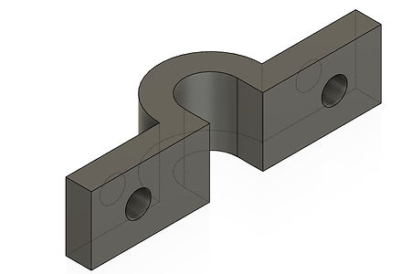
The next major hardware component we focused on this week were limit switches. These would be used as a measure to always find the home of the two threaded rods. Something was 3D printed so the limit switches would be on the top of the threaded rods. Below are pictures and videos of it.


When the pH code was implemented with all the other code ,we ran into a few problems that we are still working out the kinks on. The same goes for the GPS driving, the robot drives perfectly it just did not stop when it reached 20 feet. These issues are being constantly worked on and figuring out how to fix them.
Week 10(11/06/20 - 11/12/20)
This week there were 3 goals set out for Easy Tree. These three goals were secure pH probe, figure out relay module and why it was not working and incorporate GPS code into Easy Tree. Starting with the pH probe, we 3D printed two parts. One would be over the pH probe diameter and the other part was an L-bracket that would sit at the top of probe ensuring that it would not move up.


Next was to figure why the relay module was giving us issue. We gleaned that the issue was relay modules do not pass power through them rather they just act as switches. So to combat this we daisy chained VCC, which is 5V, to the common output of the relay module. We then also plugged the power of our load into the NC pin on the output of the relay module. Thomas tested this on a DC motor that he had and the output was turning on and off with the code,so this will have no problem with the water pump. The equivalent circuit is shown below to further analyze what is happening.

Finally the last goal was to implement the GPS code. After researching possible new routes GPS was integrated into the main code. It was calculated how much 20 feet is in longitude and latitude degrees. An if statement was added after the driving function to stop the robot after it has moved forward.
Week 9(10/30/20 - 11/05/20)
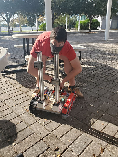
This week in progress began with a meeting in person on campus to finish mounting modules on Easy Tree. After the diligent work of campus security, we were removed from school grounds and told we needed to find a new place to work. We relocated to a nearby park mounted the pH probe, and began testing the threaded rods. We wanted to make sure that worked in unison/in order. We also mounted the distance sensor to the threaded rods to make sure they didn't lower too deep.
Afterwards, we met on a second day to mount the fertilizer pump and seed hopper. They were both tested in conjunction. The seed hopper worked according to plan, but the pump would continue to pump water even when it should not have been. Finally we attempted a trial run of the whole System working together. It was determined that the pH probe would need to be fastened tighter to the threaded rod so it would be able to penetrate the ground.


Week 9(10/23/20 - 10/29/20)
We began our week by testing the TIP120 and it's circuit. We were unable to get the circuit working properly even though we had set it up according to the datasheet. The circuit is shown below.

The next thing that we set out to do was mount the drill to the stepper motor. We wanted to get this on there so we could continue testing the robot. Thomas got some wood and wood screws along with washers to be able to mount it to the platform on the stepper motor. We decided to remove the shell of the drill. We just left the chuck of the drill attached to the gearbox which is then attached to the dc motor. This means that we will be having some wires hanging down from the stepper motor.

The next thing that we did was mount the pH sensor to the right stepper motor, we also used a small piece of 2 by 3 wood to do this. We are just going to tape the pH sensor to the wood, this will make sure that it is properly secure. As we were troubleshooting, the code to get the pH sensor to raise and lower, it started to rain. So due to unfortunate circumstances we had to leave and we were unable to get a picture or video of this working.We started to route the wires properly on the robot, that way we had more physical space on top for all of the components to fit.
Week 8(10/09/20 - 10/15/20)
We began our week by recieving a new arduino board. Due to the issues we were having with the last Arduino. We ordered a brand new arduino board and it arrived and is working properly. So with the arrival of the new board, as see below, we were able to get the code loaded onto the new board and now we were able to get the robot to drive and raise and lower the lead screws. This simulates the drill and the pH sensor.

The next thing that we set out to do was see what type of switch/relay we needed for the robot since this was the next task. Samer set out and found some results. We found that using a bjt darlington transistor with the arduino will be able to properly swtich a 5V water pump for the robot. We also ordered a relay just as a safe backup in case the BJT transistors don't work as we expected. A picture of both the parts that are coming Friday are shown below, along with the datasheet of the transistors.
TIP120

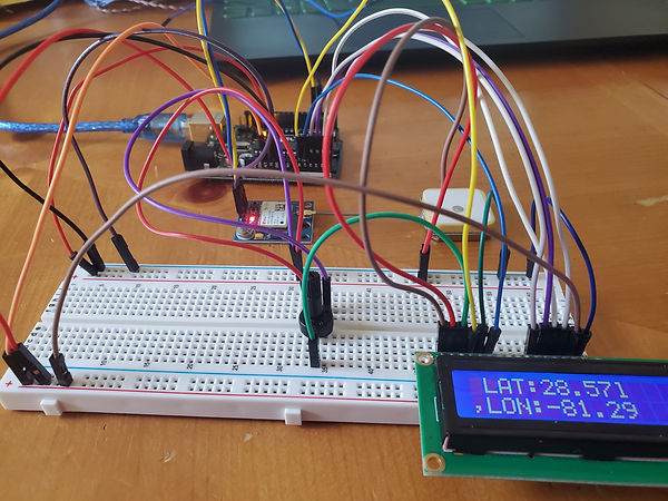
We also got the GPS code working along with it's logic. This was then hooked up to an LCD monitor to properly read the longitude and latitude, we also figured out how to store the data in variables.
Since we are going to be mounting the drill this weekend to the robot , we wanted to make sure that the drill circuit was working properly with the motor controller, so we hooked it up and removed the trigger from the drill. This will be replaced with a motor controller to control the speed. The drill functioning can be seen below.
Week 7(10/09/20 - 10/15/20)
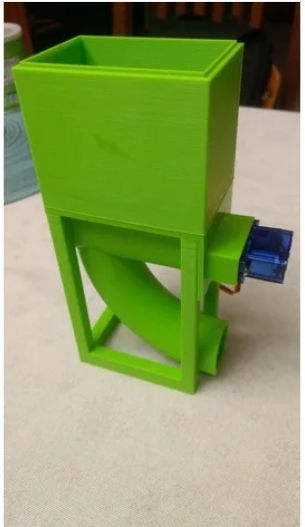
We began our week by looking into designs for the seed dispenser. We found a design online, that we thought was suitable. So using this design, we decided to print it on the 3D printer. The design can be found here below are some pictures of the design and it's components.


Then the team set out to integrate all the components together with the Arduino. We know that all the components work separately so it's a matter of compiling the code together to see where the faults potentially happen. We then met up at the school twice to collaborate on the robot. We ran into a couple of problems this week, some which were resolved and another not as of now. The first issue we ran into was that there was power being supplied to DC motors before the arduino was powered. So that was a major issue that we needed to resolve. Below we can see the circuit and pinout of the L298N module, this is the motor controller circuit. We realized that we had the keep the ENA/ ENB jumpers in place. These are enable which are tied HIGH when the jumper is removed. So to resolve the problem we just put the jumpers back in.

Then the next thing we worked on was getting the robot to drive back and fourth. Below are some pictures and videos of us working at the school. We were able to get the robot driving it's self. Which was a good goal for us to reach this week. However when we tried to get the stepper motors working with the Arduino, our Arduino started to give us some errors as to why it wasn't running. We have been troubleshooting this issue, we do not know what caused the issue. It appears that something with serial is faulty or not working properly.


The last thing that we wanted to test this week was the water pump for the fertilizer and how to integrate it with the rest of the robot. We got the pump working with the Arduino when we supplied it 5V and below is a video of Samer demonstrating it's function.
Week 6(10/02/20 - 10/08/20)
We began our week looking through every previous senior design project in search of a compass module that works. We only found one, from the 2016 group Smart Football. This proved to be fruitless, as the board they used is out of date and no longer produced.

We have decided to pursue using the GPS as a compass for Easy Tree. We ordered the board for the fertilizer module. Next we started integrating the code together. Below is an what we have written so far:
// Motor A connections
int enA = 9;
int in1 = 8;
int in2 = 7;
// Motor B connections
int enB = 3;
int in3 = 5;
int in4 = 4;
//button variables
const int buttonPin = 2; // the number of the pushbutton pin
const int ledPin = 13; // the number of the LED pin
// Variables will change:
int ledState = HIGH; // the current state of the output pin
int buttonState; // the current reading from the input pin
int lastButtonState = LOW; // the previous reading from the input pin
// the following variables are unsigned longs because the time, measured in
// milliseconds, will quickly become a bigger number than can be stored in an int.
unsigned long lastDebounceTime = 0; // the last time the output pin was toggled
unsigned long debounceDelay = 50; // the deb
//gps variables
#include <TinyGPS++.h>
#include <SoftwareSerial.h>
static const int RXPin = 4, TXPin = 3; // recieve/transfer to pin 3 & 4
static const uint32_t GPSBaud = 9600;
//TinyGPS++ object
TinyGPSPlus gps;
// The serial connection to the GPS device
SoftwareSerial ss(RXPin, TXPin);
long latitude();
long longitude();
// stepper motor variables
#define dirPin 2
#define stepPin 3
void setup() {
Serial.begin(9600);
ss.begin(GPSBaud);
// Set all the motor control pins to outputs
pinMode(enA, OUTPUT);
pinMode(enB, OUTPUT);
pinMode(in1, OUTPUT);
pinMode(in2, OUTPUT);
pinMode(in3, OUTPUT);
pinMode(in4, OUTPUT);
// Turn off motors - Initial state
digitalWrite(in1, LOW);
digitalWrite(in2, LOW);
digitalWrite(in3, LOW);
digitalWrite(in4, LOW);
pinMode(buttonPin, INPUT);
pinMode(ledPin, OUTPUT);
// set initial LED state
digitalWrite(ledPin, ledState);
// Declare pins as output:
pinMode(stepPin, OUTPUT);
pinMode(dirPin, OUTPUT);
// Set the spinning direction CW/CCW:
digitalWrite(dirPin, HIGH);
}
void loop() {
// read the state of the switch into a local variable:
int reading = digitalRead(buttonPin);
// check to see if you just pressed the button
// (i.e. the input went from LOW to HIGH), and you've waited long enough
// since the last press to ignore any noise:
// If the switch changed, due to noise or pressing:
if (reading != lastButtonState) {
// reset the debouncing timer
lastDebounceTime = millis();
}
if ((millis() - lastDebounceTime) > debounceDelay) {
// whatever the reading is at, it's been there for longer than the debounce
// delay, so take it as the actual current state:
// if the button state has changed:
if (reading != buttonState) {
buttonState = reading;
// only toggle the LED if the new button state is HIGH
if (buttonState == HIGH) {
Serial.println("will now wait 3 seconds");
delay(3000);
Serial.println("going to gps module");
gpsInfo();
delay(3000);
Serial.println("will now drive the motors");
driveControl();
delay(3000);
Serial.println("will now raise and lower the pH probe and the drill");
stepperControl();
ledState = !ledState;
}
}
}
// set the LED:
digitalWrite(ledPin, ledState);
// save the reading. Next time through the loop, it'll be the lastButtonState:
lastButtonState = reading;
}
// This function lets you control spinning direction of motors
void driveControl() {
// Set motors to maximum speed
// For PWM maximum possible values are 0 to 255
analogWrite(enA, 255);
analogWrite(enB, 255);
// Turn on motor A & B
digitalWrite(in1, LOW);
digitalWrite(in2, HIGH);
digitalWrite(in3, HIGH);
digitalWrite(in4, LOW);
delay(5000);
// Turn off motors
digitalWrite(in1, LOW);
digitalWrite(in2, LOW);
digitalWrite(in3, LOW);
digitalWrite(in4, LOW);
}
void serialshit() {
Serial.begin(9600);
Serial.println("yooo");
}
void gpsInfo() {
while (ss.available() > 0) {
gps.encode(ss.read());
if (gps.location.isUpdated()) {
Serial.print("Latitude= ");
Serial.print(gps.location.lat(), 6);
Serial.print(" Longitude= ");
Serial.println(gps.location.lng(), 6);
}
}
}
void stepperControl(){
// These four lines result in 1 step:
digitalWrite(stepPin, HIGH);
delayMicroseconds(500);
digitalWrite(stepPin, LOW);
delayMicroseconds(500);
}
Week 5(09/25/20 - 10/01/20)
This week we met up in order to get hands on experience with the other team members modules. Alongside running field tests on some of the remaining components, a hardware schematic was created in pspice alongside a layout for the Easy Tree as a whole. Most of the components were then mounted. Some of the modules (compass) still need work. We started off by making a finalized layout for each component on EasyTree.


Below are the pictures from our meeting on Sunday.


Week 4(09/18/20 - 09/24/20)
The main goal of this week was to make sure that the Easy Tree robot chassis was able to move and drive when supplying power. Below shows videos of the chassis driving, with obstacles or not.
We have preliminarily put together a layout of where main components are going to be located on Easy Tree, which is shown below.

A 3D printed battery cover has also been made so we are able to put two screws on the side of the battery touching the terminals that way we are able to get the power from the battery to the rest of the robot. The battery will be mimicking a power supply.


The pH probe was put under some more involved tests to see how it will react in different chemicals. We had to calibrate the sensor so that the readings were as accurate as possible. Below are some images of the products that were bought to test.


First we will be calibrating for a pH value of 7. Pure Water has a pH reading of 7. An example of this process running in Arduino is shown below. The red arrow indicates when and where the sensor was calibrated for that pH reading.

Next we will be calibrating for a pH value of 4. Tomato juice has a pH reading of 4. An example of this process running in Arduino is shown below.

Finally we will be calibrating for a pH value of 10. pH increase solution (Ingredients: RODI water and sodium bi sulfate) has a pH reading of 10. An example of this process running in Arduino is shown below.

Below shows timestamps of how fast the pH sensor takes to drop from a high pH to a low pH. From the screenshot below we can see that it takes about 30 seconds for it to drop.

Compass was tested profusely, in an attempt to calibrate the compass many different programs were run. Time and again, readings would either show zero or ludicrous numbers. After double checking the wiring and various codes, it was determined that the board was defective. A new one has been ordered and will arrive by the end of the week.
Week 3(09/11/20 - 09/17/20)
This week a necessary part arrived (Female BNC adapter), with it construction on the pH sensor probe could be completed. Although calibration is still required, initial tests of the pH probe and it's circuit were done to ensure proper operation. Household chemicals will be used to calibrate the pH probe to the proper sensitivity (pH 4,7 and 10).


The Matlab code was improved to fully portray how the pH values in a field are going to be represented to the end user, after Easy Tree has finished collecting data. The screenshots and code below will be used to represent pH in an easy to read heat map.


Matlab File
The motor has been mounted to the chassis of the robot, a motor mount was made in AutoCAD. The purpose of this is so the motor has some support while on the robot and does not move around during easy tree tasks.


Next on the agenda was to work on the compass sensor to get it working properly. We found some code online to help us get up and running with this sensor. Below are a few images of the sensor plugged into the Arduino board. The code is also shown below along with the serial output.


Week 2(09/04/20 - 09/10/20)
First thing was we figured out how to get the GPS working and sending data. First we wanted to just read any information off of the GPS sensor so we could tell that it was working. So the module was plugged into the TX and RX pins with no code loaded and it displayed what is seen below in the GIF. These are known as NEMA sentences.
//Thomas Quaglia
//Easy Tree 9/4/20
#include <TinyGPS++.h>
#include <SoftwareSerial.h>
static const int RXPin = 4, TXPin = 3; // recieve/transfer to pin 3 & 4
static const uint32_t GPSBaud = 9600;
//TinyGPS++ object
TinyGPSPlus gps;
// The serial connection to the GPS device
SoftwareSerial ss(RXPin, TXPin);
void setup(){
Serial.begin(9600);
ss.begin(GPSBaud);
}
void loop(){
while (ss.available() > 0){
gps.encode(ss.read());
if (gps.location.isUpdated()){
Serial.print("Latitude= ");
Serial.print(gps.location.lat(), 6);
Serial.print(" Longitude= ");
Serial.println(gps.location.lng(), 6);
}
}
}

Next I wrote some code that will read data off of the GPS module and imported a TinyGPS library that will then convert the lines of data seen in the GIF above, into longitude and latitude.
We wanted to test every electrical asset on easy tree this week. So we set out to do that. First, since it was the easiest is testing the wheel chair motor that we ordered. Below is a video showing us plugging in the wheelchair motor. Since it is just DC, we supplied it 12V positive and ground and the motor started spinning. Nothing else will need to be done here until later stages of easy tree when we start writing code to get easy tree to move.
We also wanted to test our linear lead screw, with the L298N module. So we spent 5 hours figuring out how to wire this up to the stepper motor since the motor is rated at 24V and we could only supply it with 12 Volts. But we finally got it working, plugging power into the L298N module and then plugging each phase of the stepper motor into Motor A & Motor B on the module.
The frame work also began for the robot. We had 3D printed some chassis parts and screwed them to a piece of plywood that we had.


Next we were going to work on getting the ultrasonic distance sensor working properly. Below is the circuit that Samer used to hook this up.

//Samer Al-Khub
//Testing distance sensor
const int trigPin = 9;
const int echoPin = 10;
float duration, distance;
void setup() {
pinMode(trigPin, OUTPUT);
pinMode(echoPin, INPUT);
Serial.begin(9600);
}
void loop() {
digitalWrite(trigPin, LOW);
delayMicroseconds(2);
digitalWrite(trigPin, HIGH);
delayMicroseconds(10);
digitalWrite(trigPin, LOW);
duration = pulseIn(echoPin, HIGH);
distance = (duration*.0343)/2;
Serial.print("Distance: ");
Serial.println(distance);
delay(100);
}

Next we were going to work on getting the compass sensor working properly. Below is the circuit that Samer used to hook this up.
#include <Wire.h>
#include <HMC5883L.h>
HMC5883L compass;
void setup()
{
Serial.begin(9600);
Wire.begin();
compass = HMC5883L();
compass.SetScale(1.3);
compass.SetMeasurementMode(Measurement_Continuous);
}
void loop()
{
MagnetometerRaw raw = compass.ReadRawAxis();
MagnetometerScaled scaled = compass.ReadScaledAxis();
float xHeading = atan2(scaled.YAxis, scaled.XAxis);
float yHeading = atan2(scaled.ZAxis, scaled.XAxis);
float zHeading = atan2(scaled.ZAxis, scaled.YAxis);
if(xHeading < 0) xHeading += 2*PI;
if(xHeading > 2*PI) xHeading -= 2*PI;
if(yHeading < 0) yHeading += 2*PI;
if(yHeading > 2*PI) yHeading -= 2*PI;
if(zHeading < 0) zHeading += 2*PI;
if(zHeading > 2*PI) zHeading -= 2*PI;
float xDegrees = xHeading * 180/M_PI;
float yDegrees = yHeading * 180/M_PI;
float zDegrees = zHeading * 180/M_PI;
Serial.print(xDegrees);
Serial.print(",");
Serial.print(yDegrees);
Serial.print(",");
Serial.print(zDegrees);
Serial.println(";");
delay(100);
}
The last thing we got working this week was the Matlab code for how a heat map with sample data would look in a 3D plot on Matlab using the mesh and surf functions.

Week 1(08/28/20 - 09/03/20)
Most of the week was spent just printing out 3D printed parts. All the parts for the tracks have been printed.
We met on zoom to discuss and go over the parts that were ordered and we will be meeting up this weekend to give each other the parts that we need.

While we were also printing 3D prints, we met to discuss and review the code for the Arduino to get that started early. We both got the compiler loaded on our systems.Which can be seen below and started downloading the libraries for the GPS sensor and distance sensors. Shown below is the compiler loaded on our systems and then the circuit that we will need to make for the GPS library to get it to work.


Above shows the GPS circuit

Above shows the compass circuit
We also started to look at tutorials for Matlab to start implementing the plot data of the field that the user will specify and we have found a tutorial on MathWorks that we think we are going to follow in order it incorporate this into the robot.
Week 0(08/21/20 - 08/27/20)
Since the gear and the u channel were really small we had to figure out a way to keep the diameter around 3 or 4 inches with an air gap between the teeth of the sprocket remaining an inch. We came up with the following sprocket would have 12 teeth and the air gap between the teether would be also an inch. The air gap properly equates to where the tooth will grab the chain. An example of this is shown in a picture below. Our X in this case is 1 inch.

Since we had made the sprocket now we need to make the chain again since as mentioned in the week before it was way too small. We decided that a good starting point would be his dimensions due to the fact that we now have a air gap of 1 inch. We felt that we needed to make the walls a little thicker, so we decided to make them 3/16 inches thick. Other than that we will keep them dimension ally the same.
There are two parts needed for a chain. A small link and a bigger link, they are shown below.


Also the parts that were on the budget have been ordered.
Week 0 (08/14/20 - 08/20/20)
The starting with 8/9, we started manufacturing 3D prints. After proposal we kept following the same tutorial as we thought this was the best route to go down.
So with that in mind the first thing that we have to do to produce Easy Tree is build the tracks/ treads that will hold the robot. To do this, some CAD software will be required and sent over to the 3d printer. On VegOilGuy, he used a 6 inch diameter sprocket, by .75 inches thick with 20 teeth, shown below.
For the sake of following the tutorial, this was made on CAD. The PDF of the part is included below.

So we wanted to make the sprocket smaller since this is a .75" thick sprocket and that it is massive coming in at a diameter of being 6 to 7 inches and that is a lot of material to print with a 3D printer. So we had the idea of just scaling the drawing by 0.5 so that everything would be reduced in half and we test printed this. We also made the thickness of the sprocket .25 inches, even though he used the .75 we wanted to use .25 because he was using aluminum and we are not. The result is shown below.


Due to the sprocket being reduced by a half that means the chain for the sprocket will have to be reduced as well. The dimensions of the channel are shown below. This image below shows the size of them normally.

When we reduced the size of the channel by a half we quickly realized that they were way too small, and that they would not work.